Assembling a Computer
Overview of General Safety Issues
Before beginning any assembly process, review safety procedures.
Assembling a computer is not an inherently dangerous job, but being aware of safety procedures is a good starting point.
In addition to the safety procedures, there are safety concerns with leaving the computer plugged in while working inside it.
Assembling a computer is not an inherently dangerous job, but being aware of safety procedures is a good starting point.
In addition to the safety procedures, there are safety concerns with leaving the computer plugged in while working inside it.
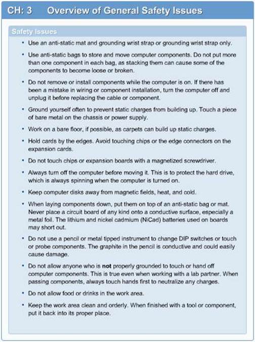
ESD Precautions
Electrostatic Discharge (ESD) is more commonly referred to as static electricity.
ESD is probably the greatest problem when a user is unwrapping newly purchased computer parts and components while preparing to assemble the computer.
Just because a discharge cannot be felt does not mean it cannot harm a computer component.
ESD is probably the greatest problem when a user is unwrapping newly purchased computer parts and components while preparing to assemble the computer.
Just because a discharge cannot be felt does not mean it cannot harm a computer component.

Creating a Computer Inventory
Importance of an Inventory
When building a computer from scratch, it is important to document all of the components and parts that are purchased.
Make sure the specifics about installation and maintenance requirements are saved, so that warranties will be valid.
Make sure the specifics about installation and maintenance requirements are saved, so that warranties will be valid.
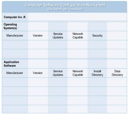
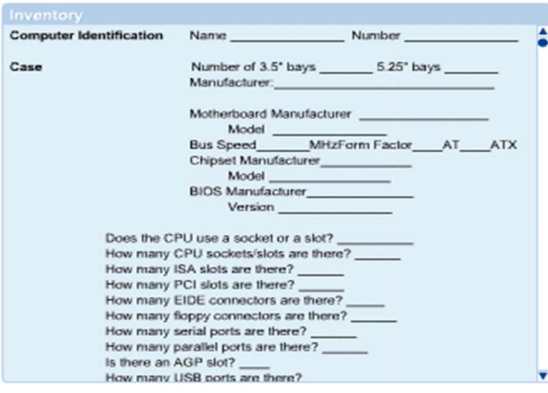
Inventory Checklist
It is important to save all the documentation that comes with the components.
Store original documentation in zip lock type bags and paper work in 3-ring binders.
Keep a notebook in which websites can be referenced with useful information related to components such as devices drivers, and so on.
Store original documentation in zip lock type bags and paper work in 3-ring binders.
Keep a notebook in which websites can be referenced with useful information related to components such as devices drivers, and so on.
The Computer Case and Power Supply
Computer Cases and System Units
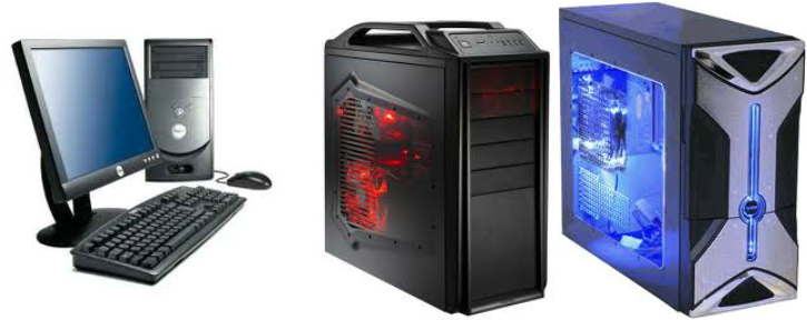
Whether buying a tower or desktop it is recommended that the unit conforms to the ATX standard and has at least a 250-watt power supply (300 watts is ideal).
Purchase a case that comes with a tray that allows easy access to the internal components.
There are three basic system unit styles: desktops, towers, and portables. Each design offers characteristics that adapt the system for different environments.
Purchase a case that comes with a tray that allows easy access to the internal components.
There are three basic system unit styles: desktops, towers, and portables. Each design offers characteristics that adapt the system for different environments.
Desktops
There are two important considerations in choosing a desktop case style for a computer:
- Available desktop space
- Form factor (describes the general layout of the computer case )
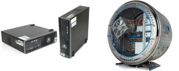
Towers
Tower cases are usually designed to sit vertically on the floor beneath a desk.
Tower cases come in three sizes:
Tower cases come in three sizes:
- Mid towers
- Mini towers
- Full-size towers
Power Supplies
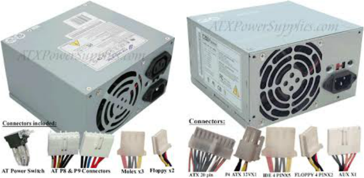
The power supply unit provides electrical power for every component inside the system unit.
There are two basic types of power supplies:
There are two basic types of power supplies:
- AT power supplies
- ATX power supplies
levels of well-regulated DC voltage for use by the system components. These are +5V, -5V, +12V, and -12V.
In ATX power supplies, the +3.3V level is also produced and is used by the second-generation Intel Pentium processors. The IC devices on the motherboard and adapter cards use the +5V level.
Be able to identify the uses for each voltage level and the corresponding color-coded wire. This will allow testing of the wires using a multimeter to determine if there are problems with the power supply.
The computer power supply produces a voltage only when it has a load. Some component must be running on the machine before a voltage can be found in the power cable connectors.
D.C Requirements of a PC
A computer system requires a number of stabilized d.c voltages to drive the motherboard and other peripheral devices and adapter cards.
The 3.3V supply line is used for modern processors and support chips that need low voltage supplies.
The +5V provides power to all TTL devices such as Logic gates and multiplexers.
The +12V line is needed to drive the motors of the disk drives and CD-ROMs.
Some applications such as a serial port require bipolar(i.e positive and negative) electrical supplies. This is provided by the -5V and -12Vrails. •-5V provide power to ISA bus cards, early PROM)
-12V provide power to some serial port circuits, PROM)
All voltages are subject to tight regulation of ±5 percent.
Preparing the Motherboard for Installation
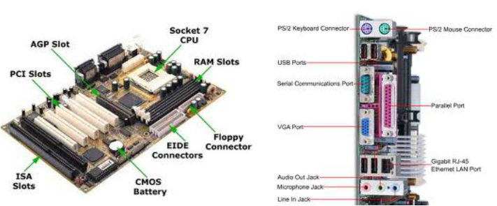
Motherboard Configuration
Location maps allow the correct configuration of the motherboard for the case controls and monitor lights on the front case panel .
For the disk controllers, always remember that a colored stripe on the data cable is pin 1.
The BIOS interface can be keyboard driven, or it can be graphical and mouse driven.
When drives are replaced, memory upgraded, or adapter boards added, the BIOS setup will need to be updated to reflect the configuration changes and saved to the CMOS chip.
The motherboard must be configured for the frequency of the installed processor.
Motherboard Jumpers
A jumper is a pair of prongs that are electrical contact points set into the computer motherboard or an adapter card.
When setting a jumper, place a plug on the prongs that completes or closes the contact.
Closing or opening the circuits establishes logic levels to select functions for the operation of the board.
When setting a jumper, place a plug on the prongs that completes or closes the contact.
Closing or opening the circuits establishes logic levels to select functions for the operation of the board.
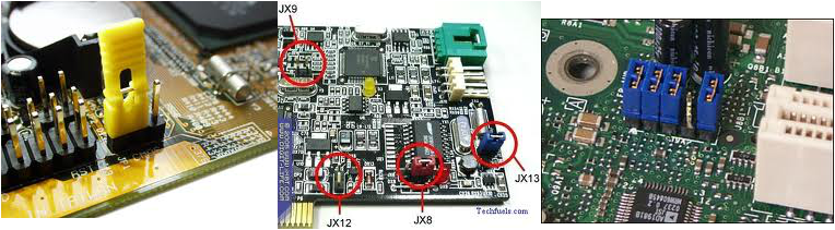
Typically, motherboard jumpers are configured by using a jumper to bridge a pair of pins that are to be connected together (to complete a circuit) on the board.
Removing or inserting jumpers on a set of pins will enable or clear a given option, as specified in the motherboard manual.
There are several additional jumper settings that may have to be set along with the general motherboard configurations:
Removing or inserting jumpers on a set of pins will enable or clear a given option, as specified in the motherboard manual.
There are several additional jumper settings that may have to be set along with the general motherboard configurations:
- BIOS Recovery
- Clear CMOS
- Password Clear
- BIOS Setup Access
- Processor Voltage
Installing the CPU
Most problems occur when the chip is hastily installed or installed backwards, which causes the chip pins to break.
There are two main types of CPU interfaces.
After installing the CPU, it is important to make sure that the right voltage is present for the proper performance of the processor.
If the proper voltage is not set, total damage to the system could occur, or the whole system will never operate correctly.
Most microprocessors can produce a lot of heat, which if not efficiently dissipated can cause the system to operate intermittently or fail completely.
One way to dissipate heat from processors is to use the heat sink and cooling fan.
There are two main types of CPU interfaces.
- Socket type
- Slot type
- Turn over the chip and inspect the pins to make sure none are damaged (bent or broken). All pins should stick straight out.
- Align pin 1 on the chip with pin 1 on the socket for a correct installation.
- Open the ZIF socket. Shift the lever slightly away from the socket, from its default closed, level position and raise it to the open, vertical position.
- Align pin 1 according to the orientation that was determined in Step 2. Insert the processor chip into the socket so that all of the pins slide into the matching holes.
- Double-check to make sure that there is no gap between the bottom of the CPU chip and the socket. If there is none, then the processor chip is properly inserted.
- Secure the installed chip, push the lever gently back down to the closed, level position.
After installing the CPU, it is important to make sure that the right voltage is present for the proper performance of the processor.
If the proper voltage is not set, total damage to the system could occur, or the whole system will never operate correctly.
Most microprocessors can produce a lot of heat, which if not efficiently dissipated can cause the system to operate intermittently or fail completely.
One way to dissipate heat from processors is to use the heat sink and cooling fan.
Installing the Heat Sink and Fan
Processors that come with the fan and heat sink already attached to them are more convenient.
These are called boxed processors.
Boxed processors cost a bit more but are safer to install since it lessens the chance of breaking the pins.
They also have better warranty coverage than those without the fan and heat sink attached.
Boxed processors are referred to as original equipment manufacturer (OEM) processors.
Installing RAM
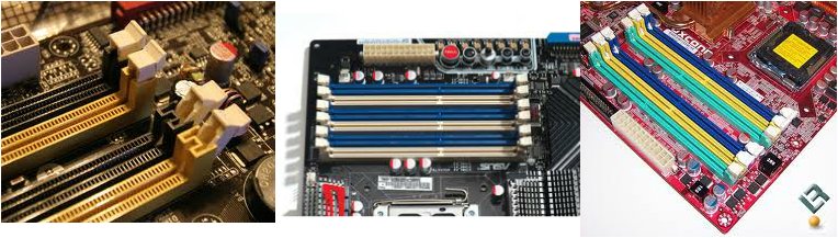
There are two types of memory modules used on most PCs: 168-pin Dual In-line Memory Module (DIMM) cards and 72-pin Single In-line Memory Module (SIMM) cards.
New motherboards do not use SIMMs. It may be found, for example, that the DIMM sockets on the motherboard map are grouped into three or four banks of one slot each.
DIMM1 and DIMM 2 are Bank 0 and Bank 1.
In some cases, motherboards have more than two slots for RAM. These slots would be DIMM3 and DIMM4. Cover the four step Installation of RAM.
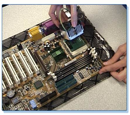
How to Install RAM
New motherboards do not use SIMMs. It may be found, for example, that the DIMM sockets on the motherboard map are grouped into three or four banks of one slot each.
DIMM1 and DIMM 2 are Bank 0 and Bank 1.
In some cases, motherboards have more than two slots for RAM. These slots would be DIMM3 and DIMM4. Cover the four step Installation of RAM.
How to Install RAM
- Find out what type of RAM is required for your desktop computer. The manufacturer can often recommend the exact RAM you need. (If you own a Dell, the Dell update software can provide a link to the exact RAM you need. There's no need to purchase it from them, however.) Find out the PC type (e.g., PC2700), the RAM speed (e.g., 333 Mhz), and the capacity of your computer (e.g., 2 Gigabytes). It is important to know how many RAM ports you have if you intend to buy more than one chip or you want to keep the chip(s) you have currently.
- Purchase RAM, which can be cheaper . A good return policy in case you purchased the wrong type is worthwhile, as well as a warranty.
- Turn off the computer and unplug it from everything.
- Open your computer case. There is often a latch on the back of the computer that has a screw in it, so you may need a screwdriver (probably Phillips). Some new computers have a latch on the top (Dells). It will be easier to install the RAM if your computer is on a solid surface on its side, with the motherboard facing up toward you.
- Ensure that you do not have static built up on your body. Static can damage computer internals. Do not wear a wool sweater, do not drag your feet on carpet, and do not rub a balloon on your head unless it's absolutely necessary. If necessary, you can purchase a small wrist band that can connect to a ground to prevent static discharge.
- Once you have the case open and are free of static, you need to locate the RAM slots on your motherboard. Most of the motherboards in computers have 2 or 4 RAM memory slots. Most RAM slots are located on the top of the motherboard, on the right-hand side. You should see something in the computer that is similar to what you purchased.
- If you have an extra empty slot, put the new RAM in that one. If there is only one slot available, push the clamps open to release the chip. The clamps are on the side and are typically white. Push them toward the sides of the computer. There is one clamp on each end of the RAM chip. Remove old memory. Hold RAM by the ends, and do not touch the chips or metal connectors. The old memory may be kept or sold.
- Look at any instructions that came with the new RAM. There may be something specific about the RAM that you need to know.
- Look at the new memory and survey the motherboard memory slots. The RAM ports should have a notch in each memory slot. Hold the RAM chip carefully by the ends or plastic parts. Do not touch the metal or chips. Line up the notch on the motherboard with the notch on the new memory.
- Press gently but firmly until the clamps close completely. You may need to push the clamps in toward the chip, but do so very gently. If the chip does not fit, do not force it. Try putting it in the other way.
- Repeat the previous steps for installing RAM if you have another chip. Additional chips may be more difficult to install because other chips reduce the amount of room for your fingers. Be careful.
- Remove dust from the computer, if it's dusty, using a bottle of compressed air. These are available at any office supply store. Do not blow air too closely at the computer. While you have the computer open, now is a good time to do this.
- Close the computer and reattach all of the cords to the computer, including the screen and power cord. Turn on the screen and turn the computer on. The computer should present a screen that shows a message about detecting new memory and the amount of the new memory. The size displayed may not be exactly how much you purchased. Operating systems calculate memory differently and some computers dedicate a certain amount of RAM to specific functions (e.g., video), decreasing the amount available. For example, you may have purchased 1 Gigabyte of RAM. The operating system may only display 0.99 Gigabytes.
- If your computer runs faster, it worked! RAM will help with opening and closing programs. You should notice that programs start faster now. If not, there may be a problem with the RAM or you have too much RAM.
- As a last check, check the system settings to make sure the RAM is okay. (In Windows, press and hold the Windows button and press the Break/Pause button on the upper-right of the keyboard. The RAM amount should appear in the lower part of the menu.) The system settings will probably say less than the amount you installed, e.g., 0.99 G for 1 G of RAM.
Installing the Motherboard
Installing a motherboard seems to be very easy, but there are many tricks involved in the process. If your motherboard isn't correctly installed you will face problems like overheating and system crashes (computer "freezing", "locking", "resiting" – you name it). This tutorial is a step-by-step guide on how to correctly install your motherboard, avoiding such troubles.

Matching Holes
The motherboard is installed in the computer case. The first step is to open the case and locate the metallic plate where the motherboard is screwed to. Normally this plate can be removed from the case by unscrewing it from the back end of the case and sliding it. You must remove it from the case to install the motherboard on it. This plate has several holes, as you can see in Figure 1.
The motherboard is installed in the computer case. The first step is to open the case and locate the metallic plate where the motherboard is screwed to. Normally this plate can be removed from the case by unscrewing it from the back end of the case and sliding it. You must remove it from the case to install the motherboard on it. This plate has several holes, as you can see in Figure 1.
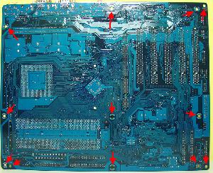
The motherboard also has several holes, as you can see in Figure 2 (They drawn in red arrows to point where the holes are located).
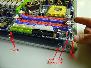
You should lay down the motherboard on the metallic plate and check which holes from the metallic plate match the holes on the motherboard, as we show in Figure 3. As you can see by comparing Figures 1 and 2, the metallic plate has more holes than needed. On the holes on the metallic plate that matched a hole on the motherboard, you will install a nut screw (more on that in a few moments). On the holes that don't match a hole on the motherboard, you will simply leave it away. Sometimes you will find some holes on the motherboard that don't match any hole on the plate. That's normal too. In Figure 3, you can see a hole on the motherboard that doesn't match any hole on the plate.
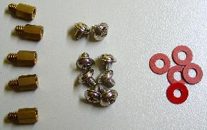
Figure 4: Screw nuts, screws and washers that come with the case.
Together with the case come a lot of small pieces. From these pieces you will need screws and screw nuts to install the motherboard. For now, take the screw nuts and install them on all the plate holes that matched a hole on the motherboard. They can be easily installed by turning them clock wise using your thumb and index finger.
Together with the case come a lot of small pieces. From these pieces you will need screws and screw nuts to install the motherboard. For now, take the screw nuts and install them on all the plate holes that matched a hole on the motherboard. They can be easily installed by turning them clock wise using your thumb and index finger.
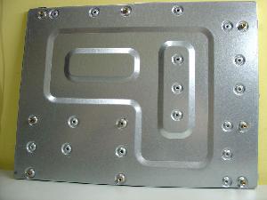
Figure 5: Metallic plate after installing the screw nuts.
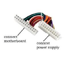
Connecting Power Supply Cables to the Motherboard
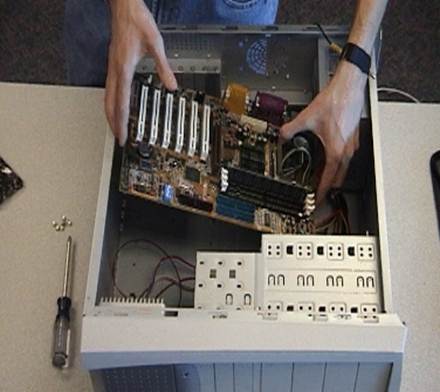
After successfully installing the motherboard in the computer case, proceed with attaching the appropriate power supply connector(s) to it.
This process is easy with an ATX (boards and power supply) because there is only one connector that is also keyed to fit only one way. Cover the steps for connecting the power supply cables to the motherboard.
This process is easy with an ATX (boards and power supply) because there is only one connector that is also keyed to fit only one way. Cover the steps for connecting the power supply cables to the motherboard.
Attaching the Hard Drive and CD-ROM to the Case
Attaching the hard drive and CD-ROM are basically similar processes.
Make sure that the interface cable will reach the drive in its intended location.
With IDE/ATA drives, the length of the cable is limited to 18" and less, in some cases.
It is much easier to configure these drives before installing them in the computer case.
Before setting the jumpers, determine the types and number of drives to install.
In a basic system that only has one hard drive, set the jumper to “master”. Some drives have another setting called “single”.
The CD-ROM is similarly easy to configure. However, jumpers may be located in different places on each drive and may even be labeled differently.
Set the CD-ROM to “master” if it is the only drive connected to the second IDE channel.
Installing the CD-ROM is not very different than installing the hard drive.
Slide the drive into the bay from the front, making sure that it is flush with the front panel, and screw it in place.
In some computer cases, particularly the mini towers, it can be quite challenging to work behind the CD-ROM because of its length and also because it is obstructed by the power supply.
Fitting the Case Together
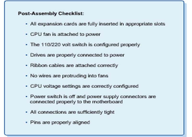
Once all the components and parts have been installed in the case, it is time to complete the PC assembly process.
Check to make sure that all of the pin 1 indicators on the cables match up with all of the pin 1 indicators on the sockets and that connections are snug.
Make sure that all of the screws are properly tightened.
When securing the case, make sure no cables or wires are sticking out or are caught between the parts of the case.
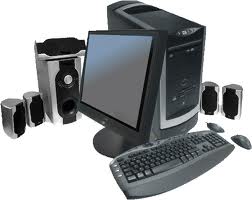
Connecting the Keyboard,Mouse, Monitor, and Power Cord
Connect the basic input and output (I/O) devices that the computer needs to start. These devices can be connected in any order.
- Connect the keyboard to the back of the case
- Connect the mouse to the back of the computer
- Connect the monitor
- Plug in the main power supply
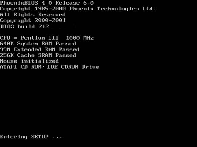
Booting the System for the First Time
What is BIOS
BIOS stands for Basic Input Output System.
It contains the program code required to control all the basic operating components of the computer system.
BIOS contains the software required to test hardware at boot up, load the operating system, and support the transfer of data between hardware components.
The BIOS function runs basic device test programs and then seeks to configure these devices.
The system BIOS and the information required to configure it is stored on a Complementary Metal-Oxide Semiconductor (CMOS) chip. CMOS is a battery-powered storage chip located on the system board.
The CMOS chip has rewritable memory since the configuration data can be changed or updated as the components or devices in the computer are changed.
Entering the BIOS Configuration
When setting up the computer for the first time, it is necessary to run the CMOS Configuration Setup utility.
Simply pressing the delete key during the opening boot sequence provides access to the BIOS on some computers.
Simply pressing the delete key during the opening boot sequence provides access to the BIOS on some computers.
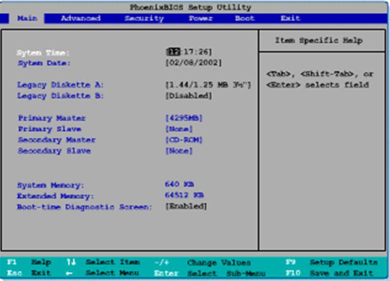
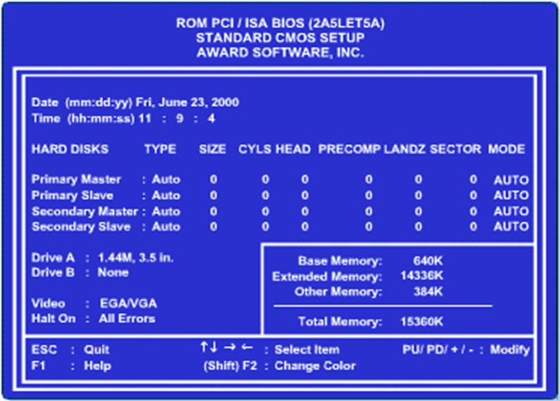
Standard CMOS Setup Screen
Standard CMOS setup screen includes the basic operating parameters that need to be set for the system to work correctly.
These BIOS features are typically universal for all PCs.
The fields available for entering configuration data that are commonly find in this screen are: Date, Time, Hard Disks, Drive A, Drive B, Video, and Halt On.
These BIOS features are typically universal for all PCs.
The fields available for entering configuration data that are commonly find in this screen are: Date, Time, Hard Disks, Drive A, Drive B, Video, and Halt On.
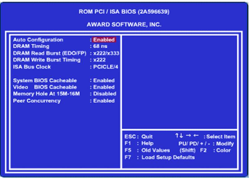
BIOS Features and Chipset Features Setup Screens
The BIOS Features Setup screen provides advanced features that control the behavior of the system.
This screen is where the system hardware can be fine-tuned for optimal performance.
The Chipset Features Setup screen allows the fine-tuning of the control parameters for the main system chipset.
This screen is where the system hardware can be fine-tuned for optimal performance.
The Chipset Features Setup screen allows the fine-tuning of the control parameters for the main system chipset.

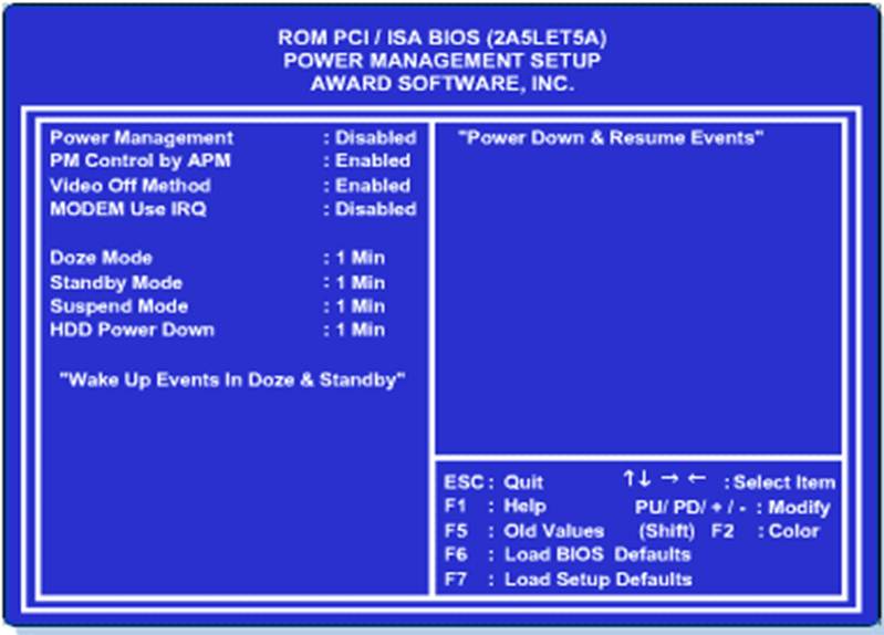
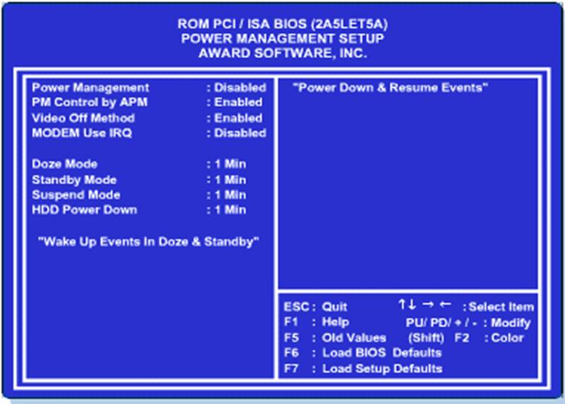
Power Management and Plug and Play screens
The Power Management Setup screen controls the optional power management for devices on the computer.
The PnP/PCI Configuration screen contains the feature settings used to control the system I/O bus and Interrupt Request (IRQ) and Direct Memory Access (DMA) allocation for ISA and PCI Plug and Play (PnP) devices.
The PnP/PCI Configuration screen contains the feature settings used to control the system I/O bus and Interrupt Request (IRQ) and Direct Memory Access (DMA) allocation for ISA and PCI Plug and Play (PnP) devices.
The “Resource Controlled By” setting when set by default to Automatic Configuration, the BIOS will automatically manage the interrupts and direct memory access channels on the I/O bus for the PnP devices to avoid conflicts with any legacy (non-PnP) ISA devices.
In general, the default settings should be used for this section of the BIOS setup when working on newer systems, because any manual configurations require a good knowledge of the bus devices installed.
In general, the default settings should be used for this section of the BIOS setup when working on newer systems, because any manual configurations require a good knowledge of the bus devices installed.
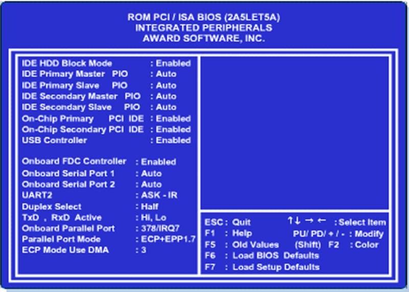
Integrated Peripherals and Fixed Disk Detection Screens
Used to configure the control of integrated peripheral support on the motherboard.
Integrated peripherals typically include such devices as the onboard floppy and hard drive controllers, USB controller, serial ports, parallel ports, and the sound card chip.
Integrated peripherals typically include such devices as the onboard floppy and hard drive controllers, USB controller, serial ports, parallel ports, and the sound card chip.
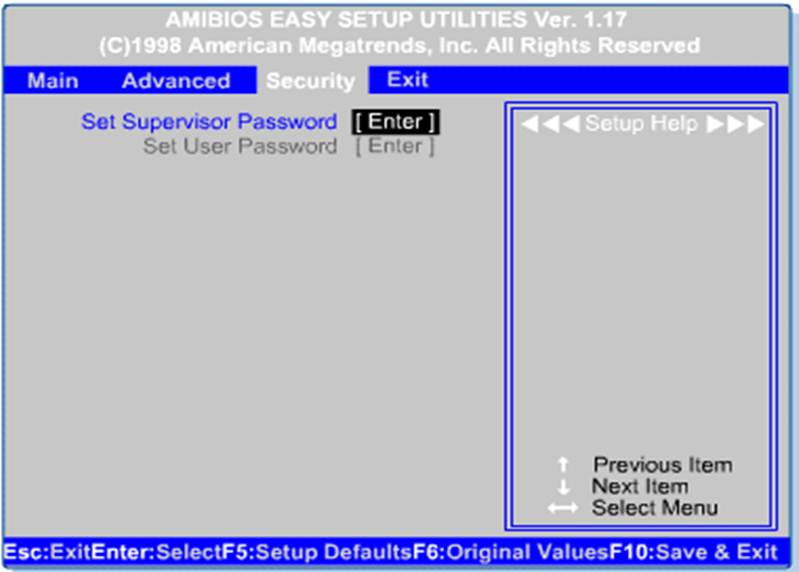
Password Screens and the Load Setup Defaults Screen
There are two password screens that will be encountered in the BIOS setup:
- Supervisor Password
- User Password
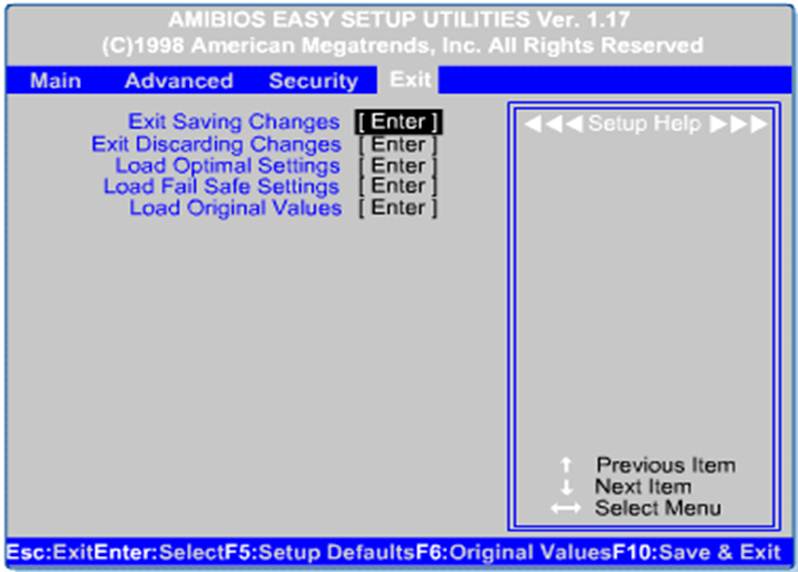
BIOS Exit Options
There are two BIOS exit options:
- Save and Exit Setup
- Exit Without Saving Setup
Start up Sequence
Whenever a computer starts up, a series of tests are automatically performed to check the primary components in the system, such as the CPU, ROM, memory, and motherboard support circuitry.
The routine that carries out this function is referred to as Power-on self-test (POST).
The POST routine provides error or warning messages whenever it encounters a faulty component
Post error codes take the form of a series of beeps that identify a faulty hardware component.
If a problem is detected, a different number of beeps will be heard, sometimes in a combination of short and long tones.
These are mainly BIOS-dependent codes. They vary according to BIOS manufacturer and even between different versions of BIOS. Problems that occur during the POST are usually caused by incorrect hardware configuration or installation. Actual hardware failure is rare.

